They said you couldn’t do it and there were times when I agreed. The 18RGU uses considerably more fuel than the Volkswagen system was willing to deliver. A lot of tinkering was required but the tangible result –a faster, much more responsive and marginally more economical Celica — seemed worthwhile. The real gain was in understanding.
The Celica broke a piston and cooked its valves on a trip from Texas to Eastern Tennessee. Admittedly, the 18RGU engine had accumulated lots of miles since installation, but the immediate cause seemed to be an off-brand of lubricating oil, labeled as meeting all new car warranty requirements. At 700 miles into the trip, the oil thinned to the consistency of water. A lean carburetor, jetted to meet CARB emission requirements, contributed.
While waiting for parts from a California race-car salvage yard (the engine has no factory support in North America), I ransacked junkyards for a Weber DGA carburetor replacement. Holley built the DGA under license for Ford, but reversed the throttle swing, which would have caused interference between the throttle cable and the chassis. Jet codes were an enigma. I decided to shunt the whole vacuum-fed nonsense and go to some form of pressurized fuel injection.
Do-it-yourself fuel injection usually involves transferring the necessary parts from an injected version of the same or very similar engine. Although I haven’t done it, updating a Chevrolet small block with throttle body or tuned port injection should be a fairly straightforward project, since most of the engineering is already in place.
The 18RGU engine has no fuel-injected successor. Whatever system selected would require lots of fitting and serious tuning. Pulsed, computer-driven systems seemed uninviting, since the old man has only a hearsay knowledge of digital electronics. What you don’t know, you have to buy. A programmable CPU – the electronic equivalent of changing carburetor jets and centrifugal advance springs — costs $2000.
I opted for a Bosch mechanical system, generally known as the CIS (Continuous Injection System). “Continuous” means that the injectors emit a constant stream of fuel, once past pop-off pressure. The earliest, or K-Jetronic, versions of the system were purely mechanical. The one selected includes a small computer to meet emissions requirements and improve cold running. Omitting the computer has no serious consequences on driveability.
Hot and cold idle rpm and, to some degree, mixture strength are manually adjustable. Hardware modifications can provide additional mixture control.
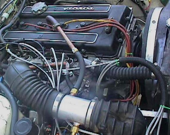
Major components – fuel distributor, throttle body, auxiliary air device, injectors, thermal/time sensor and warm-up regulator – came a from 1984 VW 1.7-liter sohc Rabbit. In retrospect, a Volvo or Saab CIS would have been a far better choice for the fuel-hungry 1.8-liter, dohc Toyota.
The conversion described here is not very elegant. Once the parts were mounted and functional the goal became to achieve an acceptable rich mixture at all speeds and loads. The 18RG was never an economical engine and oversized valves installed during the recent overhaul made it less so. I knew that an extremely rich mixture, registering something on the order of 900 millivolts on the oxygen sensor, was required to stabilize the idle. What flexible, responsive cruising might take was a matter of conjecture, but it would be far more than the 0.500 volt described in the literature as chemically perfect.
CIS Pros and Cons
The CIS is a reliable and fairly inexpensive system to work with — the high pressure pump rarely fails if protected by a filter on the suction side and supplied with clean, water-free fuel. Running the pump dry will quickly fry it. Injectors appear to be quite reliable and, to some minor extent, respond to cleaning with lacquer thinner. At the time of the conversion, new injectors listed at $38 apiece, or about a third as much as the price of more modern examples. The fuel distributor is the most expensive part, with $500 and more asked for rebuilt units. But millions of functional distributors reside in junkyards.
Because it is mechanical, the CIS is tweakable to some degree, although serious modifications are easier to talk about than to make. Bosch provides adjustments for idle and low-speed mixture control. Adapting components from different CIS applications allows room for maneuver, especially as experience is developed with the system.
On the debit side, the learning curve is fairly steep. Few professional mechanics understood the technology when it was new, and fewer still can cope with the problems of transplants. You have to do your own research.
The CIS occupies a great deal of under hood space, making for a busy engine compartment. First priority is to rout lines clear of the exhaust manifold and armored OEM lines clear of coil terminals and other voltage sources. The fuel filter should be accessible and, if under the car, adequately shielded. Tie down the heavy fuel distributor with removable brackets so that changing out the air filter does not become a major project. Mate the throttle body to the fuel distributor with any of the various OEM rubber sleeves. Couple these parts as close together as possible for good throttle response. You should install an oxygen sensor close by the exhaust manifold, whether or not you run a computer with the KE. When you’re done and all the parts are in place, it would be nice to be able to see the ignition distributor and reach the oil filter.
To my way of thinking, the worst aspect of CIS is its potential for fire. Most of the plumbing, including the feed line running the length of the car from the tank to the engine bay, contains gasoline under high pressure. OEM plastic fuel lines fail if crimped or merely as a function of age and handling. As delivered there was no automatic shutdown when fuel pressure is lost.
Like modern technology generally, fuel injection improves reliability while introducing a small, but real, potential for catastrophic outcomes. Fuel lines must be routed safety, made up to the appropriate connections, armored against abrasion with plastic sheathing, and routinely inspected.
Information Sources
The basic documentation – theory of operation and troubleshooting/repair procedures – can be had from any of a dozen sources. But one would have to resort to industrial espionage to obtain engineering data for this or any other fuel injection system.
Automotive Electric/Electronic Systems, Robert Bosch GmbH, 1988, licensed to the Society of Automotive Engineers, Inc., ISBN 0-89883-509-7. This book gives a general overview of the systems and, read carefully, reveals some of the design concerns.
How to Tune & Modify Bosch Fuel Injection, Ben Watson, MBI Publishing, I992, ISBN 0-87938-570-7. The author provides pressure data for all applications and, while skimpy on modifications, incorporates tips and shortcuts developed by working mechanics
ALLDATA. This subscription-only database is intended for technicians, but similar information on the CIS can be found in shop manuals of the 1970s and 80s.
- http://www/Google.com. Google currently lists 217,000 entries for CIS, mostly dealing with theory of operation and troubleshooting.
- Miller Fuel Injection adapts CIS to air-cooled VW engines on a commercial basis. Gary Miller probably has more experience with CIS transplants than anyone in the country and is more than happy to share what he has learned.
- Do-It-Yourself Electronic Fuel Injection hosts the EFI332 mailing list. Most contributors are interested, obcessed, with GM electronic units, but discussions of CIS and other mechanical systems are included. Bosch Manifold is a nice website with a beautifully crafted adaptation of a Volvo CIS to a Type IV VW engine.
Notes on Components
Fuel Distributor Assembly — consists of the fuel distributor (the part that mounts the cylinder injector, warm-up regulator, cold-start injector, inlet and tank-return lines),the air-flow sensor (“flap valve”) and air filter element.
All distributors have a central horizontal port in the head for fuel delivery to the warm-up regulator and four vertical injector ports. The central port also functions as a test port for delivery and control pressure readings. Gary Miller identifies three generations of K-series fuel distributors by the pattern of connections on the sides of the units. As I understand it, the view is looking down on the distributor with the center outlet in the head at the 12 o’clock position.
- First Generation — fuel filter inlet at 10 o’clock, feed to cold-start injector taken at the same port; return to tank and return from warm-up regulator share the port at 1 o’clock.
- Second Generation — fuel filter inlet at 11 o’clock; return to tank at 8 o’clock; return from regulator at 9 o’clock; cold-start injector feed at 7 o’clock.
- Third Generation (computer)– fuel filter inlet at 11 o’clock; return to tank at 8 o’clock; return from warm-up regulator at 9 o’clock;cold-start injector feed at 7 o’clock. These units, which Gary modifies, have a blocked oxygen-sensor port at 4 o’clock.
Injectors. Bosch has a special tool for removing injectors, but a large, flat-bladed screwdriver works about as well. Exercise care why prying injectors out of junkyard vehicles. Rust and heat-hardened o-rings make it easy to inadvertently bend the injector barrel.
The injectors should howl audibly and produce a flat, fan-shaped pattern; an offset pattern can be tolerated, so long as the fuel does not congeal into a stream. Injector delivery volume is critical. The Bosch test requires a container graduated in cc’s and a timed pump run. For a quick test, you can use baby food jars as catch pans, run the pump for a few seconds, and line up the jars on a flat working surface to compare the fluid levels.
Injector dribble under reduced pressure makes for difficult hot starts, never a CIS strong point. Most of the hot-start problem appears to be the result of percolation, which can be helped, but not cured, by mounting the injectors in the threaded plastic sleeves used by Volkswagen.
According to Bosch, the o-rings should be installed dry and rolled over the injector barrels. Silicone may help, since new o-rings fail upon repeated removal and installation. Normally, o-rings come out with injectors. Green (nitrile) aftermarket o-rings appear to give better service than the OEM black rings.
Fuel Filters. Some type of filter, preferably incorporating a water trap, should be installed upstream of the pump. The OEM filter should be on the discharge line and mounted where it will be accessible. Some CIS applications include a check valve, integral with the banjo-connection bolt, on the discharge side of the filter. Although the 10-mm bolt and valve assembly can thread into the inlet connection at the fuel distributor, to mount it there results in erratic performance. For the check valve to function properly, gasoline must enter the center hole in the bolt and exit through the radial holes.
Auxiliary Air Device. The open-loop, K-Jetronic version employs a thermostatically controlled air vent which automatically opens when the engine is cold. The surplus air, taken from some point between air vane and throttle plate, increases idle speed. As the engine warms, the combined effects of an electric heating element and engine heat cause the vent to close.
For the device to work properly, it should mounted on the intake manifold where it will be warmed and with the port adjacent to the connection feeding air into the engine. The line from the remaining port connects to a port at the rubber sleeve or at the throttle body, above the throttle plates. Connection pins are ungrounded, which means that you can use either of the two leads can for B+.
Warm-Up Regulator — reduces fuel pressure to richen the mixture during cold operation. It normally bolts to the engine block at some position well clear of the exhaust manifold. It can also be mounted remotely and heated by connecting heater hoses to the mounting fixture. The regulator incorporates one or more electrical heating elements, which accelerate warm-up period. Merely disconnecting the heaters has no long-term effect upon mixture strength, since engine heat finally determines pressure. Should you disable the engine-heat sensing diaphragm, the regulator will lose its “memory” and richen the mixture during hot starts.
Regulators that I have seen include a vacuum port, which is almost always a dummy. A minority use the port in conjunction with a barometric pressure sensor to lean the mixture at high altitudes.
Thermal-Time Switch. This heat sensor mounts in the coolant, preferably upstream of the thermostat. It controls the bimetallic heater strips in the auxiliary air device and in the warm-up regulator. Contacts on the thermal-time switch are normally closed and open under the dual effects of an internal heating element and coolant heat. The switch is grounded when cold and contacts are closed. Switches I have looked at have one connector pin dead grounded to the switch body and the other reading 0.038 ohms to ground. This figure represents heater resistance, which should rise to infinity when the switch is warm.
Bosch uses sophisticated time and ignition-pulse sensitive relays in conjunction with the thermal-time switch to control cold-start injector on time, idle-air port area and enrichment developed by the warm-up regulator.
In the best of all possible worlds, one would transfer the whole CIS system, wiring and all, to the receiving vehicle. Not doing that means that some other provision must be made for cold mixture control. The thermal-time switch can be wired in series with the warm-up regulator and fast-idle device, if the hot wire to the switch is connected to the switch heater and not to the permanently grounded pin. A relay, energized by the ignition switch, provides power. As mentioned earlier, low manifold vacuum normally trips the cold-start injector in my particular application. Dashboard switches enable the injector to be pulsed or completely turned off.
In passing it should be noted that a bent awl of the kind sold by Mac Tools makes quick work of the spring locks on Bosch electrical connectors.
High Pressure Lines. Gary Miller can supply the proper replacement hoses and fittings. His Aeroquip blue hose carries a 250 psi rating. The application described here uses Gates fuel injector hoses with homemade fittings (the original Bosch fittings do not mate securely with rubber hose). As mentioned earlier, Gates hose works for now, but I have reservations about its durability and the integrity of the screw-type clamp connections. You would be better advised to use Miller’s hose.
Stage 1
A machine shop in Knoxville drilled and tapped 22-mm threads in the homemade manifold-to-block adapter plate to accept VW injector mounts. The rest of the conversion was accomplished with hand tools.
The CIS fuel pump and accumulator were mounted in the trunk of the car, next to the fuel tank and forward of the battery that had lived there since replacing the original R20 engine. A relay energizes the pump during cranking and after starting when the engine develops oil pressure. A plastic Celica filter was installed between the suction side of the pump and the fuel tank. A Volkswagen CSI filter was mounted in the engine bay, just upstream of the fuel distributor.
Braided rubber fuel injection hose was used after a call to the vender established that the hose has a burst strength of 900 psi. The high pressure side of the Bosch system runs at around 70 psi. The ends of the steel fuel lines were bulged slightly with a double-upset flaring tool for hose purchase. Connections were secured with ordinary stainless steel screw clamps. So far, there have been no fuel leaks, although I would sleep better if proper high pressure hoses and connectors had been used.
Toyota quarter-inch steel fuel delivery and return lines were not changed. That may prove to be a mistake, since the VW doner used a 5/16 in. delivery line from the rear-mounted pump to engine bay.
I fabricated a plate to mount the CIS throttle body on the manifold where the carburetor had been.
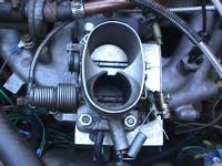
A throttle body with a large primary was initially used. A rubber elbow, salvaged from some unknown vehicle, and a short length of 3″ exhaust pipe connect the throttle body with the fuel distributor. Vacuum hose connections on the pipe supply air to the PCV and a Volkswagen device that boosts idle rpm in cold weather. The warmup regulator was mounted low on the side of the block where a mechanical fuel pump had been originally fitted. A green R-6 O-ring, intended for R-134a AC systems, seals the dipstick and prevents false air entry. The exhaust manifold was already threaded for an oxygen sensor.
The experimental, evolving state of the project meant that automatic controls were eliminated or fitted with manual overrides. Dashboard toggle switches control the fuel pump, enabling it to be turned off during starting (to prevent flooding)or to run without starting the engine (for injector and pressure tests). The cold-start injector can be switched off or energized manually with a push button switch. Phono jacks allow oxygen sensor voltage to be monitored with a digital voltmeter. Indicator lamps monitor voltage to the pump, cold-start injector and MSD ignition system.
Stage 1 Results
The engine ran, but was lean under acceleration and at speed. As a short-term fix, the VW cold-start injector was mounted on the throttle body adapter plate and connected to an adjustable vacuum switch, contributed by another Volkswagen. The switch, acting through a Toyota normally-off relay, energizes the injector under low manifold vacuum. Press on the accelerator, a lamp on the dash lights, and the injector squirts. A dash-mounted push button switch gives manual control over the injector, which may be useful this winter. Another switch enables the fuel pump to be turned off momentarily during hot starts to prevent flooding. A better solution would be to devise a means of disabling the injector during cranking. But I needed to get home to Texas.
The installation gave no problems on the 1000-mile trip, although lean steady-state mixtures punctuated by bursts of power from the cold-start injector became annoying. But the car would move out, easily hitting 90 mph during passing on two-lane East Texas roads. Fuel consumption hovered around 29 mpg. The new stainless steel valves survived the abuse without warping.
Stage 2
A digital voltmeter connected to the oxygen sensor tracked the lean condition, which began at about 2000 rpm. The mixture adjustment (via a 3-mm Allen screw that raises the air vane on its pivot) had little effect at this speed. Under heavy acceleration, the cold-start injector produced a roughly stoichiometric mixture. Transitions were abrupt, but no worse that had been experienced with the Weber carburetor. The mixture went rich during coast down.
Fuel delivery and control pressures were within specification, although fuel quantity measured at the return line tank connection was 550 cc in 30 seconds. Bosch calls for 750 cc/30 sec for the VW application. Since filters had been replaced and pump appeared almost new, the quarter-inch fuel lines might be responsible for the reduced flow. But what effect could reduced delivery have when fuel pressure at the forward distribution point appeared normal? If someone has the answer, I would appreciate the information.
The CIS regulates fuel delivery by the displacement of a counter-weighted air vane. Incoming air lifts the vane and causes more fuel to pass through the injectors. Thanks to inertia, the vane should over swing during accelerating, richening the mixture even more.
I suspected that the moving the throttle body adjacent to the air vane might richen the mixture. Close coupling should lift the vane higher at any given throttle angle and encourage over-swing during acceleration. Either that or tie a string to it.
A manifold adapter was machined from 1-inch-thick aluminum plate. I bored the plate for a press fit to 3 in. diameter exhaust pipe and undercut the lower ¼ in. of the bore to conform to primary and secondary ports on the intake manifold.
The plan was to run 3″ exhaust pipe from the plate to a 90 deg ell, with the vertical leg of the ell shortened for hood clearance and reduced the plenum volume. Cutting the ell near its apex left an oval-shaped cross-section that was welded and filled to accommodate the round pipe. The open end of the stub pipe was then press fitted into the 1-inch-thick manifold adapter plate. Epoxy secured the connection.
For additional low-speed torque, I substituted a throttle body from a later model Volkswagen, which has a smaller primary than the throttle body originally used. The new throttle body mounts to an adapter consisting of a ¼” steel plate welded to a length of 3″ exhaust pipe, with the bore of the pipe biased slightly toward the primary throttle. The open end of the pipe was mated with the ell and welded. A VW boot bridges the gap between the air horn and the fuel distributor. Eighth-inch-thick neoprene gaskets were installed at each of the two plate connections.
The engine receives PCV air from a port on the side of the throttle body. At some point, I will tee-in the cold idle hose to this line. The VW throttle cable turned out to be just barely long enough to reach the relocated throttle body.
Stage 3
Efforts made during this stage of development were aimed at increasing fuel delivery at higher speeds and during acceleration.
I disassembled the fuel distributor far enough to extract the piston. Parts were cleaned with lacquer thinner and lightly oiled. The piston showed bright wear marks, but no evidence of abrasive scoring. A severely worn piston should leak fuel into the space above the air filter and send the engine rich. That was not my problem.
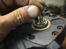
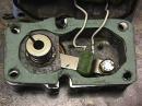
The o-ring that seals the interface between the upper (iron on the VW) and lower aluminum fuel-distributor castings was replaced with the homemade gasket shown in the photo above. This lowered the fuel ports a few thousandths of an inch relative to the piston, but the difference in height had no noticeable effect upon the mixture. Nor should it, when you consider that total piston travel is on the order of 5/8″. These devices are more loosely set up than the literature suggests.
The next step was to disassemble the warm-up regulator, mounted on the block where the mechanical fuel pump had lived. The regulator came apart in spring-loaded pieces, which took some thought to reassemble in the correct sequence. Other than a white film of corrosion on the aluminum castings, the device with its engine heat sensor and two electrically heated bimetallic strips appeared functional. Before disassembly, it developed a hot control pressure of 55 psi, within VW specifications.
I installed a .020″ gasket as a shim between the two regulator castings to reduce control pressure by increasing the distance between the thermostatically controlled push rod and regulator diaphragm. A test drive showed that the modification resulted in a marginally richer mixture, but nothing to write home about. At 2500 rpm in fifth gear, oxygen sensor voltage hovered around .20V. One needs something on the order of .45V under these conditions.
Several vendors sell an adjustable fuel pressure regulator, intended (I think) for a direct hookup to Ford injector fuel rails. One vendor said the regulator would drop pressure as low as 30 psi. A vacuum diaphragm boosts pressure under low manifold vacuum to richen the mixture during acceleration. Unfortunately, CIS control pressure is a mirror image of injector pressure. For better acceleration, you would want to reduce, not increase, control pressure. Bosch supposedly made vacuum-assisted warm-up regulators, but I have yet to see one.
I made several attempts to incorporate manual pressure adjustment into the existing warm-up regulator. The regulator was removed from the side of the engine and relocated near the intake manifold, in hopes that a linkage could be constructed to adjust pressure from inside of the car.
The heat-sensing bellows was replaced with a 1/2-inch-thick aluminum disc, pressed into the regulator housing and threaded for a 5/16″ socket-head adjustment screw. Various methods of translating screw movement to the regulator were tried, and some allowed a degree of adjustment. In an attempt to increase the range of adjustment, I eliminated the coil spring originally fitted. A brass extension on the screw bore directly against the pressure controlling diaphragm. Control pressure dropped to around 5 psi, regardless of how tight the screw was turned against the diaphragm.
The next step was fabricate a restrictor plate from a 1/2-inch diameter steel bar. The bar was drilled through from end to end, and the ends tapped to accommodate the banjo-type bolts originally used to make up the fuel lines to the warm-up regulator. A 1/8-inch diameter brass rod, pressed and soldered into the end smaller (8-mm) bolt, functioned as a plug to block fuel entry. The idea was to drill out the plug with progressively larger bits until control pressure dropped to a value that would provide sufficient fuel at high rpm.
With the plug blanked off, control pressure was 72 psi, or the same as fuel delivery pressure. Then the plug was drilled through a No. 60 (.040-inch-diameter) bit. Control pressure dropped to 7 psi, resulting in a mixture too rich to fire. I replaced original plug was replaced with another, this time drilled with a jeweler’s bit about the diameter of a human hair. Control pressure remained at 7 psi.
I’m not sure why a nearly invisible vent would bleed down all control pressure. It probably has to do with the small volume of essentially in compressible fluid in the circuit. Bosch regulates control pressure with a stainless steel disc subject to fuel delivery pressure and one face and spring force on the other. As best I can figure, the disc oscillates, opening under initial pressure and closing when the fuel vents and pressure dissipates.
Then I discovered that the valve on the CIS test gauge could function as a pressure reducer. With a light touch — just breathing on the valve — control pressure could be varied across the range from zero to 70 psi.
Stage 3 Results
At 40 psi the engine ran rich at idle with oxygen-sensor readings of more than 0.9 volts at speeds below 2500 rpm. As before, the mixture went lean at higher speeds and especially during fifth-gear passing maneuvers. Throttling the valve down to 15 psi resulted in black smoke rings at idle and flooding during hot starts. But the mixture was almost perfect at highway speeds. After much experimentation, 33 psi was settled on as the best compromise between an overly rich idle and power. The vacuum-actuated cold-start valve was still needed during acceleration at wide throttle angles. Manual control over the fuel pump and cold-start injector made starting the engine possible, but not pleasant, on cold mornings.
To summarize the lesson learned in Stage 3: do not eat at a cafe called Mom’s, play cards with a man named Doc, or attempt to adjust CIS fuel delivery by making gross changes in control pressure.
Stage 4
One of Gary Miller’s “100-hp” fuel distributors was ordered, together with another warm-up regulator. With UPS delivery charges, the cost for these parts came to $160, which seemed quite reasonable. The parts arrived in good shape and appear to have been bead-blasted.
The fuel distributor is a standard (non-computer) K-Jetronic unit, modified with the addition of a wedge in the air cone. The wedge functions as a partial shroud to reduce slippage between the airstream and the flap valve. Gary said that arriving at the right shape took a lot of dyno time.
As installed, the mixture was extremely rich, registering 0.980 volts and higher on the highway. Tweaking the 3-mm adjustment as lean as idle would tolerate dropped cruise voltage by about one point to 0.875 volts. But it was nice to have the thing running rich for a change. This was the first real breakthrough in the whole experiment.
Advised of the problem, Gary replied that “the critical thing is the area of wedge vs height.” He said that he “narrowed them at bottom to a point for lean at cruise” and that a good starting place would be to go for “50% of current width at bottom and taper from 1/2 height.” Okay.
The plan was to machine a wedge from aluminum, nylon or PVC. Almost anything would work. But examination of the part with its complex angles and turned tapers meant that one would have to begin with a thick-walled tube with an ID the size of a fuel distributor air horn. That sort of thing is not easy to find. I’m not certain, but it looks like Gary used a fuel distributor as the raw material. The OD was turned and wedges sliced out with radial saw cuts.
Sacrificing a distributor for a single part hardly made sense, so the existing wedge would have to be modified. After thinking about the problem, I decided make initial cuts parallel to lean the mixture across the whole rpm band. If necessary, the wedge would be then tapered, leaning out the low end and preserving wedge area near the upper limit of air vane travel. In this way, richness could be held in reserve until needed by less restrictive K&N air filter and other dreamed-about engine mods. Cuts were made very gingerly, 0.020″ or so at a time, and the oxygen-sensor voltage logged on the same stretch of highway.
As supplied, the rectangular wedge was 0.790″ wide. In its final form the wedge measured 0.492″ at the base, tapering to 0.552″ at the mounting-screw hole. The taper stopped at mid-height, leaving the upper half of the wedge with parallel sides for a width of .0610″.
Stage 4 Results
A 100-mile trip over the flat coastal plain that rings Houston gave oxygen-sensor voltage readings of about 0.810 volt, which sounds rich. But the engine purred and responded to the lightest touch on the accelerator. A patch of new blacktop with a rough, pebbled texture produced enough rolling resistance to pull down the output by 0.015 volt. Turning on the headlamps cost another 0.025 volt. Fuel mileage, nearly all of it on I-10, came out to 25.53 mpg. A few thousandths more off the wedge might boost that figure to 26 or 27 mpg. But I’m going to leave the calibration stand, at least for now. As the Russians say, “The best is the enemy of the good.”
Stage 5
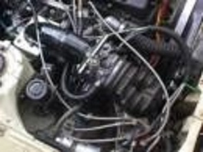
Tickled pink with the progress, I emailed a photo of the system to Gary Miller. He replied that “it is interesting to see what will run.” Okay, Gary, so a carburetor manifold cobbled up a fuel distributor looks a little weird, but it works. Sort of.
Although the engine felt healthy at 85 mph, high speed acceleration was nothing to write home about. The tiny ports on the Corolla manifold, none of which indexed accurately with the head ports, acted like a NASCAR restrictor plate. Nor did it help that incoming air had to make three right turns and branch into a candlebra before reaching the engine.
About all I could learn about intake manifold design was that runners should be of equal length, as long as possible for flat torque and as straight as possible for volumetric efficiency. Ideally runner diameter should be a few thousandths less than port diameter: the step helps prevent reversion, or flow reversals when the intake valve closes. Plenum volume should be no smaller than half and no greater than three-quarters of engine capacity. Space constraints made tuning the manifold for peak torque at a particular rpm impractical.
What material to use? Scott Frazer constructed the manifold for his Volkwagen project from semi-flexible electrical conduit, which makes sense considering the complex bends involved in plumbing a flat four. Another approach, favored by some race-car builders, is to TIG weld manifolds together from light-gauge aluminum sheeting, sort of like the way a tailor would make a pair of trousers. A few brave souls have cast manifolds in alumium or plastic. After much thought, I decided to use exhaust tubing after the example of the aircraft manifold shown at Simple Digital Systems website. The stuff is cheap, welds easily and can be mandrel bent.
Weeks of dither followed before I settled on the design pictured. The four 1/2″ tubing runners make up to a 3″ OD plenum, whose volume amounts to 43% of the engine capacity. Each pair of tubes terminates into an adapter plate, secured to the engine with 1/8″ thick neophrene gaskets. The neophrene should offer some heat insulation. In retrospect, I should have used 4″ exhaust tubing for the plenun, which would have matched the spread of the throttle blades. Three-inch tubing does not quite accommodate the spread of the throttle-body bores, which means that the secondary throttle is partially masked when wide open. The cold start injector mounts to the back of the plenum and the cylinder injectors plug into 3/4″ bar stock stubs, machined to match the the ID of the plastic Volkwagen injector holders used in previous configurations. > Mounts angle at 38 deg, a figure than was dictated by the swivel limit of my milling-machine vise. Backyard manifolds sure ain’t rocket science.
In order to simplify construction, the rubber elbow on top the fuel distributor was positioned at engine intake port height. Because of vertical space limitations, the plan was to remove the air filter box from under the fuel distributor, seal the bottom of the distributor with an aluminum plate, and mount the air filter remotely. PVC elbows and piping would connect the filter to a hole the aluminum plate directly under the distributor flap valve.
Once the manifold was installed, there was no room left in the engine bay for the filter and its awkward plastic plumbing. So much for the plans of mice and men. Flexible ducting would have simplified the hookup, but the stuff available locally is paper-thin and leaks at the connectors.
For want of a better idea, I trimmed 1″ off of the bottom of the original filter housing. That lowered the distributor enough so that the rubber elbow could make up to the throttle body. About half of the filter pleats are exposed now, which probably will make for a noisy intake.
Stage 5 Results
Success at last! El carro es mas fuerte, smooth as baby’s bottom and, while the 1 1/2″ runners should have cost some low-speed torque, improved volumteric efficiency more than compensates. The only problem is that the mixture is richer than before, registering 0.80v at 70 mph cruise. I suppose that lower pumping losses in the new manifold translate as greater lift on the fuel-distributor flap valve at any given rpm. A few thousandths shaved from the Gary Miller’s wedge should bring the mixture back to around 0.75v, at which the engine seems happiest.
And while we’re on the subject of oxygen sensors, there are published charts that purport to cross-reference O2 voltage readings with air/fuel ratios. But this data is highly suspect: commercial O2 sensors do not have this sensitivity. GM TPI systems read anything less than 0.45v as lean, and anything more than 0.55 as richer than stoichiometric. The condition of the spark plugs are a far more precise indication of mixture strength.
Except for a few housekeeping details, the project is finished, and the question arises whether the exercise was meaningful. Performance has improved: the old Toyota runs better today than it ever has. Parts that were dying in a junkyard have been utilized, which is a good feeling, a kind of victory against entropy. On the other hand, conversion to fuel injection was not easy and there were times than I would have dropped the whole project had a useable carburetor been within easy reach. What has come out of it is knowledge of a kind that difficult to quantify but which seems valuable. One can learn about the Bosch CIS and induction systems by reading about them, but the knowledge attained by actually working on and modifying these systems is deeper and more immediate than the knowledge one gets at second hand. We have to do in order to learn.
