Diesel fuel contains 10% to 15% more heat energy than gasoline and, because of the high compression ratios of diesel engines, is burned more efficiently. Add to that the lower cost of the kerosene-like fuel and the appeal of diesel aircraft engines becomes obvious. Other advantages are the reduced fire hazard presented by the heavy oil fuel and the promise, not always fulfilled, of the better reliability of diesel engines.
On the other hand, diesel engines are heavy for the power they produce. Injection occurs late, near the end of the compression stroke. A diesel engine must turn fairly slowly to provide the time necessary from the fuel to vaporize and the vapor to mix with air. Gasoline engines do not have this rpm handicap, since the fuel vaporizes quickly and has ample time to mix during the intake and compression strokes. Until friction or loss of volumetric efficiency intervene, the faster the engine turns, the most power it produces:
hp = torque x rpm ÷ 5252
In addition, the forces generated by diesel engines invite massive construction. Pistons and connecting rods must be heavy to withstand the force of compression and of fuel detonation. These heavy parts, which reverse direction twice during each crankshaft revolution, create imbalanced forces that require heavy crankshafts and cylinder blocks to contain.
That the Packard diesel played fast and loose with safety factors and yet could keep a plane in the air continuously for 84 hours was a stellar example of engineering chutzpah. Never mind that the vibration and smoke prostrated crews and passengers. That Junkers engines made trans-oceanic flights safe, routine and pleasant must be counted as one of the great engineering triumphs of the last century.
We’ll begin this account with an airship engine.
Beardmore Tornado
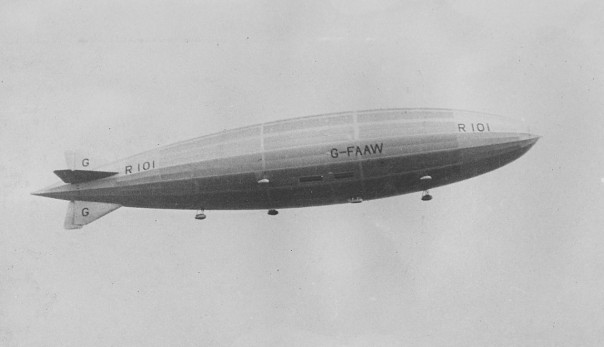
Diesel engines first went airborne in 1929 aboard the British R-101 airship. The 770-ft-long dirigible was an imperial project, intended as a troop transport to bind India more closely to British rule. It could accommodate a company of infantrymen and their gear. There was even talk of carrying a fighter plane that could be launched and retrieved in flight. Diesel power was specified because warm climate increased the fire hazard posed by gasoline. The cooler exhaust of diesel engines and compression ignition may also have been reassuring for designers of a hydrogen-filled gas bag.
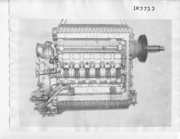
The original plan was to use seven Beardmore six-cylinder engines each weighing 2200 lb and producing 600 hp.[1] Development stalled and it was decided that the R-101 would be powered by five 3200-lb, 700-hp inline Tornado engines. These engines were cobbled together from two four-cylinder railroad engines by means of an aluminum block and cylinder head. When the light-metal parts failed, Beardmore reverted to cast iron for the block and steel for the cylinder head.
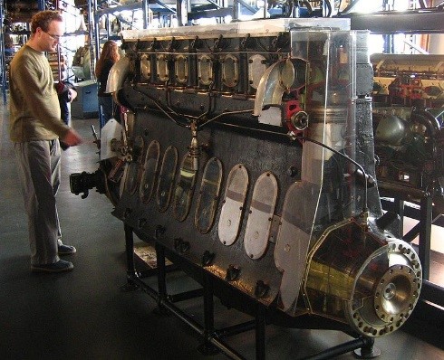
Weight increased further when it was discovered that torsional vibration, worrisome at idle, went into resonance at 950 rpm. Straight-eight crankshafts twist. The designers responded by increasing the crankshaft bearing diameter by three-quarters of an inch, adding additional main bearings, strengthening bearing webs and fitting a spring-loaded damper to the drive end of the crankshaft. A flywheel was later added. But the vibration persisted and Beardmore derated the engine. As delivered, the Tornado weighed 4773 lb and had a maximum power output of 650 hp at 935 rpm. Power was further reduced to 585 hp at 890 rpm for continuous duty. To further compromise the installation, the Tornados employed 40-hp gasoline starting engines, which required droppable fuel tanks and associated plumbing.
It should also be mentioned that the Tornado was steam cooled, which turned out to be a technological dead end as Rolls Royce would discover with the Goshawk.[2] Steam pockets act as insulators and very likely contributed to the cracking experienced with the aluminum heads on the first-generation Tornados. At any rate, the R-101 saga demonstrates the difficulties encountered when industrial engines and the habits of mind these engines engender are applied to aircraft propulsion, even when the aircraft in question is a dirigible capable of lifting 27 tons.
Packard DR-980
In September, 1928, a four-place Stinson Detroiter became the first heavier-than-air aircraft to fly under diesel power. [3] Its nine-cylinder, air-cooled, radial Packard DR-980 (Diesel Radial 980 CID) was intended as a replacement for the Wright J-5 Whirlwind, then the state-of-the-air aero engine that, among other of its accomplishments, had taken Lindberg across the Atlantic. Packard calculated that a diesel-powered Ford trimotor would have a fuel cost of a third of a cent per passenger-mile.
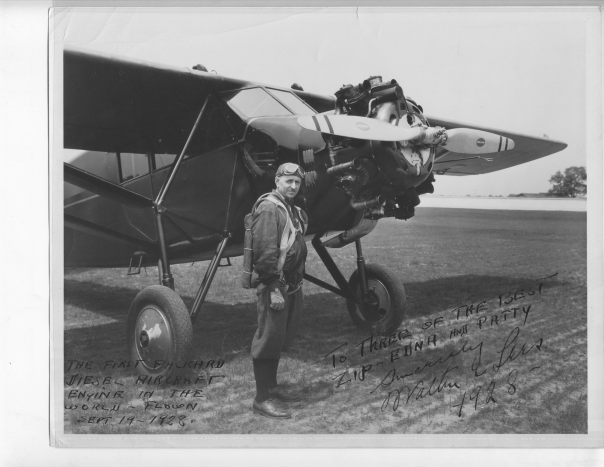
Packard promoted the engine with celebrity endorsements and record-breaking flights. Because a diesel engine runs with surplus air, a diesel engine it loses less power at high altitudes than a non-supercharged spark-ignition engine. The 225-hp DR-980 was calculated to develop 130 hp at 20,000 ft [4] . The power output of a naturally aspirated SI engine drops by half at that altitude. Consequently Ruth Nichols was able to set a new world altitude record of 19,928 ft with a DR-980-powered Lockheed Vega. Walter Lees flew a diesel Bellanca CH-300 for more than 84 hours non-stop. These dramatic successes earned the Packard Motor Car Company a Collier Trophy in 1931.
Everybody, with the possible exception of the sardonic chief designer, Lionel Woolson, was fooled.
|
|
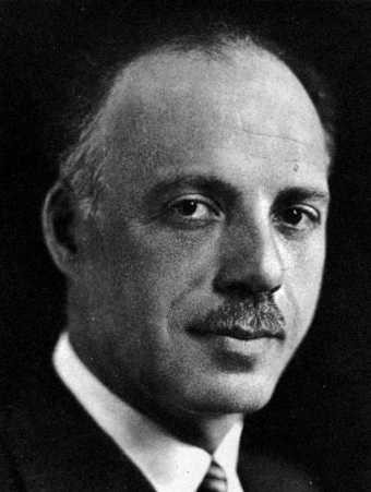
Woolson was a trained aeronautical engineer, a skilled pilot, and a captain in the U.S. Army Air Service Officer’s Reserve. He also had the verve of a man who believes Lady Luck is on his side.
And he needed luck with the DR-980, which had so much against it:
- The Packard Motor Car Company had no diesel experience and very little experience with state-of-the-art aircraft engines. The Liberty aircraft engines Packard built during the First World War and in the updated 2A-2500 configuration were hypertrophic auto engines designed for ease of production. The 1924 cast-block aluminum 1A-1500 was the company’s attempt to build a real aircraft engine capable of competing with the Curtiss D-12. [5] Production ended with 29 units.
Hermann Dorner (1882-1963) was brought in to assist with the design. His demonstration engines, capable of turning 2000 rpm, seemed to have gotten him the job. But Dorner’s practical experience with diesel engines was limited to construction of a dozen or so single- and twin-cylinder micro-cars of unknown functionality. - Packard was in a hurry. The DR-980 project can be dated from August 18, 1927, when Dorner was hired. Thirteen months later Walter Lees made the first test flight. That test flight was the signal for Packard to begin construction of a 300,000-square-foot factory capable of turning out 6000 engines a year.
- As a bolt-in replacement for the Wright J-3, the DR-980 had to stay within Wright dimensions and replicate its performance, which meant a specific weight of no less than 2.26 lb/hp. The Beardmore Tornado, the only other flying diesel, weighed 8.16 lb/hp.
| Packard DR-980 | Wright J-5 | |
| Horsepower (rated) | 225 | 225 |
| Dry weight (lb) | 510 | 510 |
| Overall diameter (in.) | 45 11/16 | 45 |
| Specific fuel consumption (lb/hp-hour at cruse | 0.40 | 0.60 |
| Cost | $4025 | $3000 |
Source—Meyer, Robert B., “The First Airplane Diesel Engine: Packard Model DR-980 of 1928,” Smithsonian, Washington, DC, 1964.
Design features
The basic architecture of DR-980 – nine radial cylinders, aluminum pistons, H-section master and slave rods, and ball-type main bearings, cam rings at the rear – was conventional. However, certain design features
smack of desperation.
Crankcase
The magnesium crankcase, variously described as weighing 28 or 34 lb, initiated the use of large magnesium castings in aircraft and other engines. A removable bulkhead, or diaphragm, machined to a precise fit in the crankcase cavity, supported the aft main bearing.
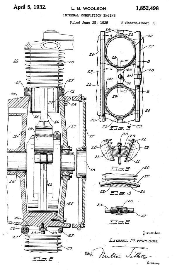
Cylinder hold-downs
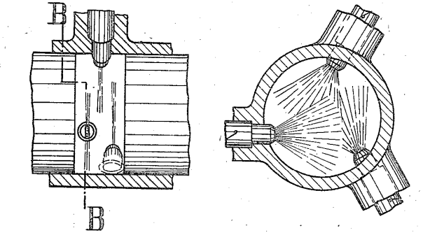
On June 25, 1928 Woolson filed for a patent for a novel method of attaching the cylinder barrels to the crankcase. Rather than employ flange bolts, the cylinders were secured with a pair of steel bands. The forward band was positioned over the leading edge of the crankcase and the aft band over the steel diaphragm to distribute cylinder stresses as compression throughout the light-metal casting. Three-quarter-inch turnbuckles between each cylinder generated the preload. Initially flange bolts were also employed, but by 1930 the bolts were omitted.
It’s probable that the bands, said to be made of stainless steel, stretched. Mechanics routinely had to tighten the turnbuckles and at least one cylinder came adrift in flight.
DR cutaway showing crankcase diaphragm (17) and cylinder hold-down bands.
Cylinders
The upper ends of the steel cylinders were sealed with integral caps that formed the roof of the combustion chamber. The aluminum heads mounted against the cylinder caps, an arrangement that imposed a thermal barrier against combustion heat. Such “poultice” heads had gone out of fashion for SI engines, but compression-ignition engines can benefit from the heat retention. Voids cast on the underside of Jumo 205 pistons had a similar function.
Mono-valve
Because a diesel engine injects fuel during the compression stroke, Woolson was able to combine intake air and exhaust functions into a single valve. The mono-valve opened during the intake stroke to admit air, closed during the compression and expansion strokes, and opened on the exhaust stroke. While some weight was saved, the major advantage was to eliminate the hot spot associated with a dedicated exhaust valve. The mono-valve arrangement also accorded with Woolson’s design philosophy. Once when flying with Walter Lees, Woolson confided “that he someday wanted to make an engine with one moving part.”[6]
The exhaust exited through short stacks with their forward ends open to receive ram air. When Lees complained that the he had to make a dead-stick landing because the engine refused to throttle down below 1500 rpm, Woolson responded with characteristic swiftness. By the next morning technicians had mounted butterfly valves on three of the air intakes. Denying air to the affected cylinders reduced idle speed to a tolerable level.
Even so, throttling intake air was an expedient that did not address the basic problem. The engine was feeding off lube oil, probably as the result of a poor piston-ring seal. Subsequently much work was done on piston rings, culminating with pistons that had two compression and four scraper rings.
Unit injector
As the name suggests, a unit injector combines an injector nozzle with a high-pressure pump. In the case of the DR-980 the pump drove through a pushrod actuated by a cam-ring assembly at the rear of the crankcase. The pilot throttled the engine by rotating the cam ring. Plunger stroke length and fuel delivery were at their maximum with the pushrod centered under the plunger. Tilting the pushrod reduced its effective length with a corresponding reduction in plunger stroke.
Most advanced diesels of the period employed multi-plunger “jerk” pumps with each plunger serving one engine cylinder. However, there were problems with this arrangement: fuel pipes had to be the same length, which was inconvenient for a radial engine, and pressure waves in the piping affected fuel delivery. Unit injectors eliminated most of these difficulties and provided redundancy, since the failure of one would not affect the other eight cylinders.
Dorner’s contribution was to design a unit injector capable of supporting high engine speeds. At 1800 rpm, the pump mechanism underwent an acceleration of 15,000 ft/sec2 to complete fuel delivery within a 0.004-second window. Although Packard did not release pump specifications, with a volumetric efficiency of 75% the engine would require 20,000 parts of air per one part fuel at full load. In other words, pump displacement would be one twenty thousandth of cylinder displacement. At idle, delivery would be reduced to one part fuel per 100,000 parts air.
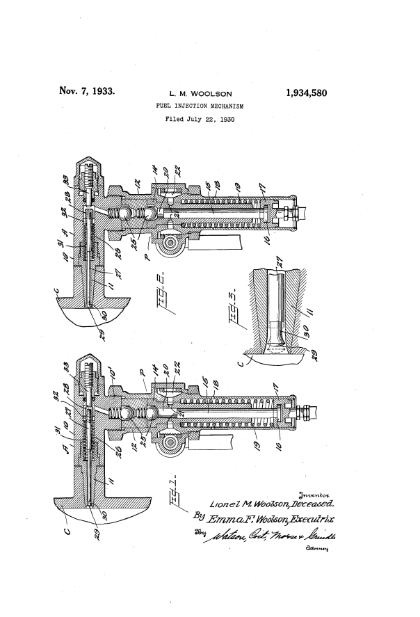
A spring-loaded Bosch-pattern pintle valve moved outward under fuel pressure to initiate injection. But, unlike Bosch practice, the pintle did not fully seat. According to Woolson, the idea was to bleed air from the fuel stream. Internal check valves prevented compression and combustion gas entry. Other manufacturers bled air through a return line between the nozzle and fuel tank.
Shock attenuation
Because of high cylinder pressures, Woolson incorporated spring-loaded crankshaft counterweights, an idea that would be widely copied. He also encased the propeller drive in rubber.
Problems
Some problems were the sort that one can expect from a novel design. Because the engine developed 500-psi cranking pressure, some sort of mechanical starter was mandatory. The prototype DR-980 was fitted with a shotgun-shell starter, which was replaced by a Heywood air unit. Production engines employed electric starters powered by a pair of batteries. Pilots complained that long fights were necessary to recharge the batteries.
As mentioned earlier, piston rings gave considerable trouble. At one point, Packard considered using gapless rings, similar to the full-circle “fire rings” fitted to the Junkers Jumo 205. The 50-hour military acceptance test was interrupted by a series of mechanical failures, including broken valve springs. In time, these difficulties would almost certainly have been resolved.
Other, less tractable problems can be attributed to the combustion process.
High cylinder pressures
In order to compete with the Wright J-5 and other spark-ignition engines, the DR-980 was fueled to generate a maximum cylinder pressure of 1500 psi, or more than 15 times its average cylinder pressure. The ratio of maximum pressure to bmep for the Wright was about five to one. Since the engines weighed the same, many experts had doubts about the Packard’s reliability. Harry Ricardo suggested that Packard had played fast and loose with the safety factor. [7]
Pilots and passengers felt the high cylinder pressure as vibration so intense that Ruth Nickols lost seven of her ten flight instruments during the course of setting the new altitude record. Because of the brief operational history of the DR-980, the effects of high cylinder pressures and the resulting vibration on engine components and airframes is unknown. Woolson would probably have used rubber-dampened motor mounts for which he received a posthumous patent.
Exhaust smoke and odor
The DR-980 trailed black exhaust smoke. Some smoke was inevitable, since all diesels emit soot-laden exhaust when operated at full power. Modern diesels are detuned to meet opacity limits. The Stinson was painted black, a color choice that would have disguised exhaust streaks made more pervasive by the absence of a collector ring. The exhaust had to be dispersed before the mono-valve opened to admit air.
The exhaust also had a pungent odor arising from incompletely oxidized hydrocarbons and aldehydes (including formaldehyde) that would have been most pronounced during cold starts and taxying. Ruth Nickols complained that the odor “permeating my luggage and clothes” sickened her copilot and made it embarrassing to appear in public.[8]
Sooty, odoriferous exhaust is prima facie evidence of poor combustion. To understand why DR-980 emitted raw or partially oxidized fuel requires a brief foray into diesel theory.
Diesel injection is usually considered to consist of four phases, or fractions:
- Onset of injection during the compression stroke.
- Ignition delay as fuel droplets mix and vaporize in contact with hot cylinder air.
- Premixed combustion. Once vaporization is achieved, the fuel charge spontaneously ignites to create a sharp rise in cylinder pressure and heat. Premixed combustion occurs, or should occur, as the piston rounds tdc on the expansion stroke.
- Diffusion burning. Fuel delivery normally continues for the first 10 or 15 degrees of the expansion stroke. Temperatures are such that the fuel vaporizes and ignites upon injection.
As indicated previously, each DR-980 cylinder was served by a unit injector that consisted of an integral plunger-pump and discharge nozzle. The nozzle had a single, rather large orifice partially masked by a pintle valve that opened under pump pressure. Takashi Suzuki reports that injector pressure was only 70 atm (1029 psi) and not 6000 psi as suggested by Woolson and repeated by Meyer.[9] Assuming that Suzuki is correct, the combination of large orifice and low pump pressure would have produced large, slow-to-evaporate fuel droplets.
In contrast, modern C-series Cummings injectors operate at nearly 15,000 psi and discharge through nozzles with ten 0.2-mm discharge orifice. European auto engines employ even smaller orifices and fuel pressures that can exceed 30,000 psi.
The DR-980 employed direct injection (DI). That is, the injectors discharged directly into the cylinders without the intermediary of a precombustion chamber. DI made for a lighter, more compact engine and promised thermal efficiency, since a precombustion chamber would bleed combustion heat. But direct injection compromised fuel distribution. For proper combustion, fuel and air molecules must distribute themselves homogenously throughout the cylinder. Overly rich and overly lean zones result in incomplete burning and high levels of soot, aldehydes and other noxious emissions.
Dorner, consciously or not following the example of Hesselman and M.A.N., depended upon air turbulence for mixing. M.A.N. exhibited a four-ton DI truck at the 1924 Berlin Auto Show which received much comment in the press. The intake valves had shrouds on their undersides to impart swirl to the air charge by directing it tangentially against the curved cylinder wall. In addition, the flat rims on the deeply dished pistons “swished” air inward as tdc was approached. These air movements were intended to break up the fuel spray and distribute it throughout the cylinder. However, the results must not have been satisfactory, since M.A.N. reverted to indirect injection on subsequent engines.
Packard pistons were similar to the M.A.N. design in that both were dished to reflect the fuel stream toward the upper cylinder where it would be impacted by air currents. The flattened rims of the pistons provided swish. Dorner provided swirl by angling the inlet ports. Port area was reduced upstream of the valve to accelerate flows into and out of the chamber.
Suzuki, who was experienced in these matters, doubted that Packard’s attempts at generating air turbulence were adequate. Turbulence would have been even less effective at low engine speeds, which helps to explain the difficulties in obtaining a smooth idle that Woolson alluded to in several of his patent descriptions.
Results
Lionel Woolson, smiling sardonically in the photographs, came up with rapid-fire solutions for starting, idling, excessive lube oil consumption, torsional vibration and the myriad difficulties associated with radical departures. He was a genius of improvisation. But the central contradiction posed by the hastily conceived alternative to what was arguably the world’s finest aircraft engine could not be overcome in the time available. Packard had gotten involved in a project beyond its depth.
Woolson died on April 23, 1930, when his diesel-powered Verville monoplane crashed into a hillside near Attica, New York, during a blinding snowstorm. Although the engine was not implicated, the death of its creator spelled the end of project. How many engines were built before the plant closed in 1933 (viii) is unknown. Dorner, who was in a position to know, put the figure at 25, Robert Neal doubted that production totaled more than 100 units. Packard put blame for the failure on external forces– the Depression, high-octane av-gas, the market shift to larger, more powerful engines – but the real culprit was corporate hubris.
[1] Old Machine Press, https://oldmachinepress.wordpress.com/2013/11/04/beardmore-tornado-diesel-airship-engine/
[2] Interesting Engines: The Rolls-Royce Goshawk, http://www.spannerhead.com/2013/01/28/interesting-engines-the-rolls-royce-goshawk/
[3] First Flight of a Packard Diesel, http://home.earthlink.net/~ralphcooper/pimage21.htm
[4] Nebesar, Robert J., “Supercharging the Aeroplane Engine and Increasing Speed at Altitude,” The Aeroplane, Dec. 25, 1931
[5] Packard 1A-1500 Wikipedia, https://en.wikipedia.org/wiki/Packard_1A-1500
[6] First Flight of a Packard Diesel, http://home.earthlink.net/~ralphcooper/pimage21.htm
[7] Meyer, Robert B., Packard Model DR–980 of 1928, p. 39/ http://www.sil.si.edu/smithsoniancontributions/AnnalsofFlight/pdf_lo/SAOF-0001.2.pdf See also Neal, Robert, Neal, Robert., “Packard as an Aero Engine Builder: The Packard Diesel,”AEHS, http://www.enginehistory.org/
[8] Meyer, p. 29.
[9] Suzuki, Takashi, The Romance of Engines, SAE, Warrendale, Pa., 1997, ISBN 1-56091911-6
Junkers
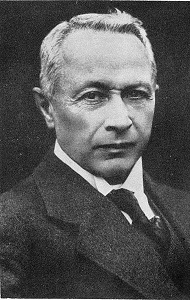
Hugo Junkers (1859-1935) had two passions: all-metal monoplanes and diesel aircraft engines.
Progress toward these goals proceeded in an evolutionary fashion, that is, by trial and error. Successful approaches were built upon and, if shown to be dead ends, ruthlessly discarded. Pragmatism ruled with little or no emphasis upon creating theoretical constructs. Open-minded, “try and see” subservience to nature produced surprising results.
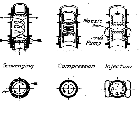
Opposed Pistons
Origins of Jumo aircraft diesels go back to 1889 when Wilhelm von Oechelhauser asked young Junkers to collaborate on an opposed-piston, two-stroke gas-fired engine. The cylinder contained two pistons articulated from the same three-throw crankshaft. The upper piston, connected to the crank by external connecting rods, also drove a reciprocating pump that pressurized air on one side of its piston and gas on the other.
Oechelhauser gas engines had a single crankshaft and “side-saddle” connecting rods. As the lower piston fell on the expansion stroke, it uncovered a row of exhaust ports. The cylinder blew down, venting itself to near atmospheric pressure.
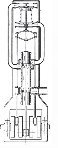
A few degrees of crankshaft rotation later air entered through the scavenging ports in the upper cylinder to purge exhaust residues that remained. Further travel of the upper piston opened the fuel-inlet ports. Once the cylinder was charged with air and fuel, the pistons rounded their external dead centers, ports closed and the compression phase began. As the internal centers were approached, an electric spark fired the mixture and the cycle repeated itself.
Single-crank, opposed-piston engines were probably cheaper to manufacture than conventional types, since a single liner served two pistons. And, of course, there was no valve train and no cylinder head, a part that frequently failed during that period. The connecting rods, 180⁰ out of phase, neutralized most loads that would otherwise be taken out through the main bearings and crankcase.
Balance was good, but less than perfect. Because the side connecting rods were longer than the central rod, the angles of the two rods and the acceleration forces acting upon them were unequal. But perfect balance meant little for engines that turned 150 rpm or less and developed bmep’s of around 60 psi.
During this period, Junkers developed his approach to applied research which he maintained throughout his career. Describing work on supercharging, a contemporary wrote,
He decided from the very beginning to explore experimentally to what limits in supercharging one could go while still maintaining the efficiency of the gas engine. … Initially, he isolates, based on a wealth of experience, the basic problems, which have to be solved individually before one can start with the synthesis of the practically useful machine. For the solution of individual problems, he develops experimental devices of surprising originality and simplicity.[1]
Detailed record keeping was also part of the formula and included artifacts. The Jumo facility would maintain a comprehensive collection of failed pistons and cylinder liners. Racked in pigeonholes with test results attached, the parts were accessible to engineers, who could handle them, run their fingers over the wear spots and, hopefully, come to a deeper understanding than reading numbers from test results would provide. Touching things might seem quaint to modern engineers, trained as they have been to flee the concrete. Junkers technicians stood closer to Giambattista Vico, who said “we can truly know only what we make.”
Oechelhauser engines, such as the twin-cylinder 600-hp example supplied the Horde iron works in 1899, found a ready market. Most were fuel by illuminating gas, although some were adapted to run on the highly corrosive waste gas from blast furnaces. By early 1910, Beardmore had manufactured 28 of the engines totaling 26,000 hp under license.
Stationary and marine engines
Work on diesel engines, begun shortly after the turn of the century, centered on previously ignored aspects of combustion. Junkers began by igniting air-fuel mixtures in sealed pressure vessels, known as bombs. With baseline data in hand, Junkers then subjected combustion to turbulence by means of a pendulum-mounted piston. The final phase of the investigation was to determine the effects of pressure. For these experiments he constructed a compound engine capable of producing 250 atm (3550 psi). Junkers discovered that heat transfer, then assumed to be almost constant, accelerated sharply with increasing pressure.
Junkers, with eight years of research behind him, then turned his attention to building demonstration diesel engines to be licensed to established manufacturers. His first oil engines followed the Oechelhauser single-crankshaft, double-piston formula. The 1908 engine had two horizontally opposed cylinders and developed 150 hp at 220 rpm. Throttling the exhaust converted the scavenge pump into a supercharger to boost bmep from 10 atm (142 psi) to 15 atm. Power output showed a corresponding increase, which was an important feature for marine engineers, who expected to be able to over-stress steam plants during emergencies.
By 1910 the engine was converted into something approximating double action with the addition of tandem pistons. Junkers also developed controls that allowed the operator to vary injection timing, duration and injector-valve lift for individual cylinders. That level of control enabled these early engines to approximate Carnot’s stipulation that cylinder pressure should remain constant as the piston falls. By manipulating the compressed-air starting valves, the operator could stop the engine and reverse it in six seconds, which was another important feature for maritime applications.
While not central to the story, the work on coal-tar fueled engines seems worthy of comment. The opposed-piston engine could, it was argued, easily burn coal tar, a petroleum substitute distilled from soft coal. Both French and German authorities hoped to substitute domestically produced coal tar for imported petroleum. The 850-mm by 1050-mm M.A.N. battleship engine, a 10,400-bhp colossus that stood 7.4 m (24.3 ft) tall, was delayed for months into order to convert it to coal tar.
Coal-tar distillate requires large amounts of heat to ignite. But once combustion gets underway, any additional fuel injected tends to explode. Engine must generate enough heat to initiate combustion and then, somehow, cool the cylinder enough so that the subsequent fuel charge would burn normally.
A small percentage of crude oil facilitated ignition. The problem of cooling the cylinder below the explosion threshold of coal-tar explosion remained. According to Junkers, single-piston engines were at a disadvantage in this regard. These engines injected against the piston top or, in the case of horizontal injections, skimmed it surface. The high-pressure fuel stream scrubbed off the insulating patina of dead gas that normally clings to the piston crown. Without the benefit of this insulating cover, the crown bled enough heat to into the fresh fuel charge to cause it to explode.
The Junkers spray pattern created by horizontal injectors expended itself in the combustion space between pistons, leaving the blanket of insulating gas undisturbed. Cold tar would then burn normally.
Junkers had entered the marine and stationary engine market at a propitious time, when two-stroke engines were becoming popular. Uniflow scavenging, with air entering one end of the cylinder and exiting out the exhaust ports at the other end, helped to redress the imbalance in fuel efficiency between two-stroke and four-stroke engines. In addition, the absence of a cylinder head improved thermal efficiency. The Junkers tandem engine of 1912 developed 1000 hp, or 3.49 hp/liter without recourse to scavenge-air supercharging. The M.A.N. 1000-hp engine, introduced a year later, developed a miserly 0.86 hp/liter.
Applications
In 1912, Wester A.G. installed a pair of license-built 850-hp tandem-piston Junkers engines in the merchant vessel Primus. But this first maritime application did not turn out well. Without so much as a shakedown cruise, the owners replaced the diesels with a steam plant. The reason for this expensive retrofit is unknown, although marine engineers of the period had serious reservations about heavy-oil engines. Similar engines, but with only two pistons per cylinder, were fitted to the Arthus von Gwinner and appear to have given good service. These 817-hp (607-kW) units burned 0.43 lb of heavy oil per hp/hour 263 g/kW-hr) and exhibited a mechanical efficiency of 74%. Other licensees included A.E.G., Noble, Du Jardin and Wm. Doxford and Sons. After the war, Doxfords built 16 Junkers marine engines in the 2000-3000-hp range, engines that set new standards for fuel economy.
As war approached, Hugo Junkers, disillusioned with licensees, founded Junkers Motorenbau at Magdeburg to produce stationary and light marine engines. The control achieved by in-house manufacturing was essential for grand projects such as aircraft diesels.
Aircraft
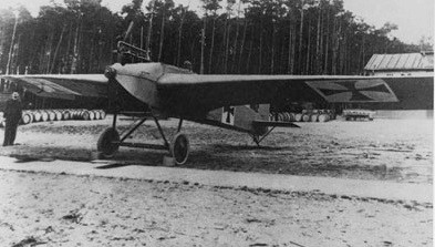
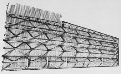
Junkers became interested in heavier-than-air flight sometime around 1908 when the Wright brothers demonstrated their airplane to European audiences. With typical thoroughness, he began wind-tunnel testing of airfoil shapes with a sphere that was progressively elongated into more elliptical shapes. During this period he also began work toward an all-metal airplane. The Ente (“Duck”) with corrugated steel wings first flew in the summer of 1912.
During the war Junkers Flugzeug- und Motorenwerke AG continued working to bring metal aircraft about. The J-1, the world’s first all-metal airplane, was sheathed with the soft iron used for electrical transformer armatures. It would barely fly, but Idflieg, the office responsible for military aircraft acquisition, took the J-1 as evidence that metal aircraft would soon be in production. Junkers saw the airplane as merely a step on the way toward a system that would encompass all-metal aircraft, improved engines – a category that included diesels for long-range aircraft – and the tooling and skills required to realize these goals. The elements that made up the system had to be developed in unison. Nothing by way of tangible results would come about until all was in place [2]
In October, 1917, Idflieg, having lost patience with an aircraft factory that had turned itself into a research institute, forced Junkers into partnership with Anthony Fokker. Junkers-Fokker-Werke, or Ifa, was marginally more productive and turned out 184 Cl.1 low-level attack planes and a handful of D. 1 all-metal fighters.
But the partnership with Fokker, an ambitious fellow on the make, underscored the conflict between Junkers’ research interests and the demands of the command economy. When the shooting stops, Junkers’ operations had accounted for only 210 of the 47,931 aircraft produced by Germany during the war. And having contributed so little, the wily old professor then walked off with Ifa, the largest airframe manufacturer in the country. Junkers was unapologetic about his lack of patriotic fervor. He viewed
“his creations and his firms as concentrated expressions of invention and quality . . . . Subordination and command economies – like those of the World War – were horrifying to him. From this perspective he often spoke of how lucky Germany had been to lose the war. Junkers viewed the war’s end as the end of an epoch of Armaments, the overcoming of class, hierarchy and ossification, of militarized economies and compulsory state intervention, of stupidity and intellectual narrow-mindedness, of bureaucracy and uniformity.”[3]
Such an attitude amid postwar starvation, the humiliation of Versailles, the talk of dolchstoßlegende, revolution in Berlin, hyperinflation and the rumble of defeat further antagonized the authorities.
Aircraft diesels
| Type | Year | Bore and Stroke | Displacement | C.R. | Takeoff power | RPM | BMEP | Weight | Lb/hp | Piston speed |
| Fo3 | 1926 | 140 mm by 2 x 210 mm | 32.33 L (1973 cu in.) | 619 kW (830 hp) | 1200 | 9.45 atm (138.8 psi) |
930 kg (2050 lb) | 2.49 l | 8.4 m/sec (1654 ft/min) | |
| Fo4 (SL1) | 1928 | 120 mm by 2 x 210 mm | 28.5 L (1739 cu in.) | 16.6:1 | 441 kW (600 hp) | 1600 | 5.81 atm (85.4 psi) |
800 kg (1763 lb) | 2.93 | 11.2 m/sec (2205 ft/min) |
| Jumo 4 | 1931 | 120 mm by 2 x 210 mm | 28.5 L (1739 cu in.) | 16.6:1 | 530 kW (711 hp) | 1800 | 6.12 atm (90 psi) |
750 kg (1653 lb) |
2.32 | 12.6 m/sec (2480 ft/min) |
| Jumo 204 | 1931 | 120 mm by 2 x 210 mm | 28.5 L (1739 cu in.) | 17:1 | 537 kW (720 hp) | 1800 | 6.20 atm (91 psi) | 750 kg (1653 lb) | 2.30 | 12.6 m/sec (2480 ft/min) |
| Jumo 5A,B, C* | 1932 | 105 mm by 2 x 160 mm | 16.6 L (1015 cu in.) | 17:1 | 404.5 kW (542 hp) | 2100 | 510 kg (1124 lb) |
2.07 | 11.2 m/sec (2205 ft/min) |
The primary obstacle to putting diesel engines into the air was weight. Marine engines for surface vessels had weight-to-power ratios of from 150 lb/hp (68 kg/hp) to 250 lb/hp (115 kg/hp). Submarine engines, the beneficiaries of intense state-sponsored development, averaged around 40 lb/hp (18 kg/hp). Before a diesel could power a heavier-than-air machine, its weight would have to be reduced to something like 2 lb/hp (0.9 kg/hp).
A secondary obstacle was ignition delay – the time between the start of injection and ignition – that limited diesel speed to a few hundred rpm. To develop reasonable amounts of power, ways had to be found to atomize and vaporize heavy oil more quickly. For example, to operate at 1000 rpm, ignition had to occur within 0.001 second of the onset of fuel delivery.
Until the war ended in 1918, Junkers personally directed research, first at Versuchsanstalt fur Ὂlmotoren in Aachen” and later at Dessau. Subsequently, a cadre of talented engineers, men such as Otto Mader and Dr. Johannes Gasterstadt, took responsibility for aero engine development. At this point, the architecture of diesel had been decided upon and detail engineering became the norm.
According to Dr. Gasterstadt, the Fo1 (F for Flugzeug) of 1915 established the rough outline for aero engine development. These engines would have:
- Two slightly out of phase crankshafts driven by spur gears. Cranks were timed to give the exhaust crank a slight lead over the scavenge crank. While the inherent balance of the engine suffered, this expedient enabled the exhaust port to open earlier than the scavenge ports and close after the scavenge ports. Consequently scavenge air could provide a degree of supercharge. In addition, out-of-phase cranks increased the time the exhaust ports remained open, since the exhaust piston slowed as it neared its external dead center.
- Angled transfer ports to impart swirl to the air charge. Spiral scavenging, as this was called, reduced fuel consumption on a 1914 test engine from 179 g/hp-hour (0.386 lb/hp-hour) to 159 g/hp-hour (0.350 lb/hp-hour).
- Solid (airless) injection operating in excess of 1000 psi. Multiple injectors, deployed around the periphery of the cylinder, discharged fuel in flat, fan-shaped and easily dispersible patterns.
The Fo2 appeared in 1916. Developing 450 hp from six 115-mm by 150-mm cylinders, the engine and the JuG1 passenger plane that it was intended to power were aborted by Treaty of Versailles restrictions. The 1800-rpm rated speed came about by the expedient of a gasoline-fueled and spark-fired prechamber, which then ignited the heavy fuel oil. Such “semi-diesels” were quite common.
.
Fo3
Concomitant with the founding of Junkers Motorenbau A.G. in 1925, work began on the five-cylinder, 32.33-liter Fo3 under the direction of Otto Mader and Johannes Gasterstadt. The decision to construct a one-ton, 800-plus-horsepower proof of concept suggests that the optimism that accompanies fresh projects had taken hold. Only later would the difficulties become apparent.
Previous Junkers engines were built up from multi-piece castings. The Fo3 broke new ground by integrating both crankshafts and the gear train into a single and highly complex casting made of silumin, an aluminum alloy developed at the request of Hugo Junkers. The addition of silicon (14% in the early commercial version) lowered the melting point to produce castings of high dimensional accuracy without the discontinuities associated with conventional (Cu and Zn) light-metal alloys. Silumin has better tensile strength than these alloys, weighs about 10% less and exhibits excellent corrosion resistance. Modern applications include Porsche crankcases, Nikon camera bodies and outdoor hardware.
The Fo3 was reported to have delivered 830 hp at 1200 rpm during brief and, one suspects, flash dyno runs. With a weight of 930 kg (2050 lb), it developed 2.49 lb/hp.
Fo4
Designers must have realized that the Fo3 had exhausted the knowledge base accumulated from experience with industrial plants. With the aid of a pair of single-cylinder, opposed-piston lab engines, Mader and Gasterstadt set out to learn more about fuel injection, charge turbulence, scavenging, heat transfer and other variables affecting performance. This effort, which was reminiscent of experiments that Junkers had conducted before constructing the 1908 engine, was remarkable. A prototype locks things in so that further development becomes something akin to piano tuning. It takes great courage to go back to fundamentals.
Three years later these investigations resulted in the Fo4 (also known as the SL1) and, after minor modifications, as the Jumo 4. The new engine weighed 130 kg (one source says 160 kg) less than its predecessor and turned 30% faster. It set the pattern for subsequent Junkers aero engines and was the first to become airborne in a heavier-than-air machine. On August 30, 1929 a Fo4 propelled a F24 transport plane from Dessau to Cologne. The 360-km flight was uneventful, in spite of the condition of the engine that had been run hard during ground tests.
However, type certification did not proceed smoothly. The Fo4 failed its first test and two years passed before it passed its second test. Pistons gave most of the problems.
Fo-4 Design features
The Fo-4 established the pattern for subsequent engines.
Vibration
The Fo4 had six cylinders to better balance the centrifugal moments and smooth torque impulses. Since the out-of-phase crankshafts made perfect balance impossible, developers were content to reduce vibration to tolerable limits. However, the crankshaft was un-counterweighted, which resulted in a secondary shaking force that had to be taken out by the seven main bearings. Only late in Jumo 205 production would counterweights be introduced.
It is interesting to note that a Packard DR-980 tested by DVL (Deutsche Versuchsanstalt fur Luftfahrt) exhibited a critical vibration at 700 rpm, well below its flying speed. The lack of vibration was attributed to spring-loaded counterweights and cushioned propeller flange.
Weight reduction
Drive gears were narrowed, crankcase covers were cast in Elektron, a magnesium alloy 30% lighter than silumin, and the crankshaft hardened to accept direct contact with the roller bearing mains. Bearings on the earlier engine had run on inner races and were capped by heavy oil-retention shields.
Expensive and slow to be delivered in the custom sizes needed, anti-friction main bearings were considered the best option at the time. Babbit bearings cracked and disintegrated under pressures of 150 kg/cm2 (2134 lb/in.2), pressures that were easily exceeded in compression-ignition engines.
While I cannot be certain, it seems likely that the connecting-rod big ends rode on leaded-bronze bearings, fused to the rod shanks and caps. Wrist-pin bearings were almost surely in the form of splash-lubricated needles as found on the 205.
Internal cooling
The Fo4 had 120-mm bores, 20 mm less than the Fo3, to shorten the thermal path from the center of the piston crowns to the cylinder walls. Forged Y-alloy pistons, in lieu of the cast-iron pistons used earlier, also assisted in chamber cooling. Y-alloy, a copper-nickel aluminum alloy developed during the war by the Royal Aircraft Establishment, had since become a popular choice for pistons.
Pistons incorporated a chamber, partially filled with oil, under the crown. As the oil splashed about, it transferred heat to the piston skirts. While Junkers patented this approach to piston cooling, it does not appear to have been original to him. The 1000-hp Sulzer-Diesel shown at Turin in 1911 cooled its pistons in the same manner.
Grooves milled on the wet cylinder liner OD’s acted as cooling fins to displace heat from the combustion chamber.
Cylinder liners
Forged nitralloy cylinder liners incorporated multiple rows of circular scavenge ports and eight large exhaust ports. Initially researchers secured the liners at their mid-points to give the ends freedom to expand. However, it was found that securing the liners from below with threaded lock rings gave better results. Seals consisted of synthetic rubber O-rings, which proved to be flexible enough tolerate liner expansion.
Ultimately (the date is uncertain) liner Ods were cadmium-plated and the serrated areas chromed to control the erosion generated by cavitation.
Timing gear mounting
Originally the spur gears that coupled the crankshafts and transferred power to the propeller and accessories were fitted to shafts running on ball bearings pressed into the crankcase. Bearing problems led to the use of stationary shafts. However, the bushings used to secure the shafts to the light-metal casting worked loose. The solution was to mount the shaft in wedge-shaped bushings with enough preload to compensate for the severe torque loading experienced by the gears and the thermal expansion of the casting. The use of a wedge in soft metal to contain such large forces was a remarkable achievement.
Scavenge pump
Because the scavenge pump had a peripheral speed of 200 m/sec (656 ft/sec), the rotor should have the highest possible ratio of yield point to specific weight. Duralumin, Elektron and alloy steel are about the same in this regard. Duralumin was selected both to reduce overall weight and to simplify machining.
Jumo 4/204
Early examples of the Jumo 4 were credited with 600 hp, a figure later upped to 750 hp. Making its appearance in 1931, this engine was the first of the series to use leaded-bronze main bearings. The exact composition of the material has been lost, but 66% CU, 3% Pb, and 1% Fe is a reasonable approximation. Such bearings exhibit resistance against rupture and, so long as copious amounts of oil are available, good wearing qualities. Lubrication failure brings lead to the surface to give short-term protection against shaft scoring and seizure.
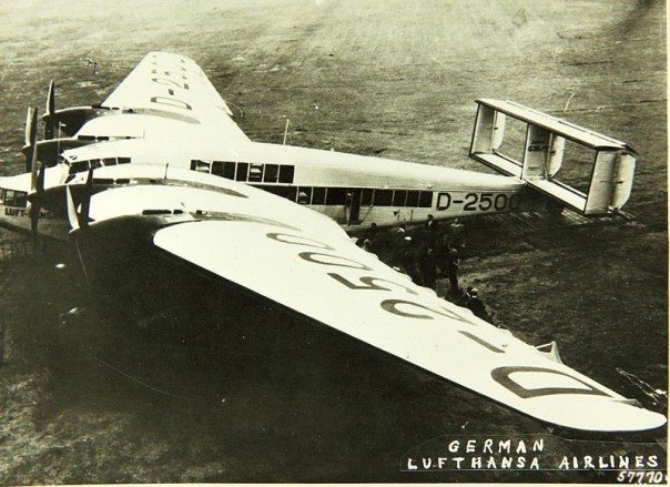
The Jumo 4 was quickly followed by the 204 with power output progressively increased from 650 to 720 hp. In 1931 this engine made history as the first Junkers diesel to enter regular commercial service. But deliveries were slow and, Lufthansa reverted to Jumo 4 engines when converting a pair of G38 airliners to diesel power in 1934. One of these magnificent machines crashed without fatalities and the other, used as a troop transport, was destroyed on the ground during the Crete campaign. Lufthansa also fitted type 4 engines to a few F24 cargo and passenger planes.
Jumo 5
The Jumo 5 of 1932, a smaller, more power-dense version of 204, Tooling at Dessau was set up to produce engines with 105-mm bores, 160-mm strokes and 145-mm cylinder centers, dimensions that would be shared by all versions of the 205 and the 207A, B and C
The prototype Dornier Do18a seaplane was flying with these engines when it went down in the Baltic.
Jumo 205 and subsequent models
The 205A, a close cousin of the Jumo 5, was introduced in 1933 and certified a year later. It remains the only diesel engine to be used successively in commercial service and the only one to have had military application.
Concerns about piston reliability limited output to 550 hp at 2100 rpm for the A and possibly the B versions. The 205 C was rated at 600 ps (equivalent to 592 SAE hp). The D and E were significantly more powerful. Production of the 205 series is believed to have ended in 1940 with an output conservatively estimated as 1500 units.
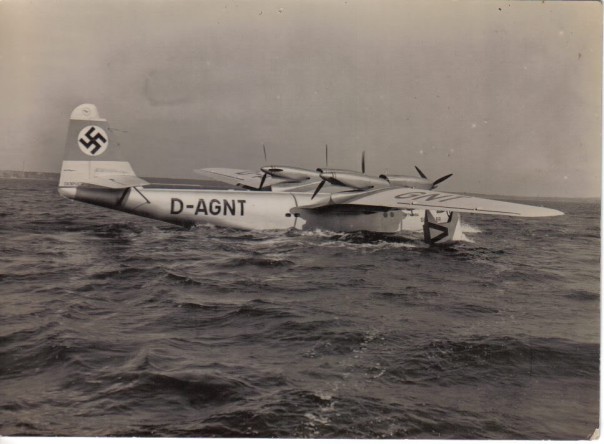
205C-powered Blohm and Voss Ha 139 and Dornier seaplanes went into regular trans-Atlantic service in 1936. Hundreds of crossings were made, many of them launched from shipboard catapults to increase the payload. By mid-1938 Deutsche Lufthansa had 48 205C and type 5 diesels, each of which averaged 400 operational hours a year. Engine life was estimated at 1000 hours with TBO of 250 hours. Pistons and crank bearings required most attention, but these components could be changed in situ with the engines mounted in their airframes.
The 20% weight penalty associated with two diesel engines on the Dornier Do.18 amounted to only 7% of the 880 imp gal fuel load and would be burned off after a few hours of flying time. Maximum range when flying at 112 mph was 3542 miles. Range dropped to 3100 miles at 137 mph. Range of the four-engined Ha 139 was similar, although the aircraft flew some 20 mph faster than the Dornier. According to the airline, the Jumo 205C had a specific fuel consumption of 0.375 lb/hp-hr in all types of service, making it 15% to 20% more efficient than Otto-cycle engines.
In 1934, the Nazi government sponsored the design of the Junkers Ju 86, a quasi-passenger/medium bomber powered by a pair of 205C engines. The shortcomings of the Ju 86D-1 became apparent when five of the aircraft were assigned to the Condor Legion during the Spanish Civil War. It was an unstable platform, under-powered and, so far as the engine was concerned, maintenance-intensive. By 1939, the aircraft was confined to the training role. A number of these planes were exported, minus their diesel engines. The Hungarians, for example, purchased 66 Ju 86K bombers and fitted them with license-built Gnome-Rhone 14K double-row radial engines.[4] Other than Dornier reconnaissance seaplanes, the 86D-1 was the only significant military application for the 205C engine.
The 207, a turbocharged derivative of the 205, also went into regular, although limited, production. Developing as much as 1000 hp at 3000 rpm, the 207 powered high-altitude reconnaissance variants of the Ju 86. The Ju 86R, introduced in 1942, had an effective ceiling of 39,360 ft (12,000 m).
Some low-priority diesel research continued until 1945, By war’s end, Otto Maderwerk, the engine development section at Dessau named for its late director, had 2760 employees, only 60 of them involved in diesel development. Even so, this relatively tiny staff produced a series of impressive prototypes, including the 68-liter, 24-cylinder, 48-piston, 4-crankshaft Ju 224 that developed 4500 hp.
After the war, essential features of the 205 series were incorporated into several stationary power plants and at least five military ground-transport engines. EcoMotors International, a start-up venture with funding from Bill Gates, has recently developed an aircraft diesel that, in so far as its basic architecture is concerned, could have come off Professor Junkers’ drawing board.
Series produced diesel-powered aircraft 1935 – 1943
| Type | Engines | Production dates | Number produced |
| Blohm and Voss Ha 139 | 4 x Jumo 205 | 1937 – 1938 | 3 |
| Dorner Do 18 | 2 x Jumo 205 | 1935 – 1940 | 173 |
| Dorner Do 26 | 4 x Jumo 205 | 1938 | 6 |
| Junkers Ju 86 | 2 x Jumo 205 | 1935 – 1939 | 548 total, 476 with diesel power, many of which were subsequently fitted with BMW 132f engines. |
| Junkers Ju 86 R -1 and P-1 | 2 x Jumo 207 | 1942 – 1943 (conversions of earlier models for high-altitude reconnaissance) | Some 40 P versions built, R version production na |
Main sources: Vajad, F. A. and Peter Dancey, German Aircraft Industry and Production, 1933-1944, SAE, Warrendale, PA, 1996 and the Hugo Junkers Homepage, http://www.junkers.de.vu
Epilogue
The Junkers complex had a difficult passage with hyper-inflation, Versailles Treaty restrictions on aircraft production, and the worldwide Depression. One of the worst financial episodes was an abortive attempt to build military aircraft in Lila, near Moscow. What little money was available went into research. In 1926, Jumo received 600,000 marks in developmental funds for diesel and BMW-based Otto aircraft engines. Three years later the research budget was increased to 2,300,000 marks, most of it earmarked for what became the Jumo 204 diesel. In 1931, Ifa and its sister enterprises verged on bankruptcy. The Weimar Republic agreed to a bailout on the condition that the old man step down. Junkers held them off until the Nazis arrived.
The old man was arrested, threatened with a list of charges including high treason, and interrogated for six hours until at 2:00 am on 18 October, 1934, he signed over majority control Jumo and Ifa to the Reich. [5] After a year of house arrest, Hugo Junkers died on 3 February, 1935, his 76th birthday. The Reichluftsministerium awarded the prosecutor shares in Ifa worth three million marks.
Appendix
A close look at the 205C
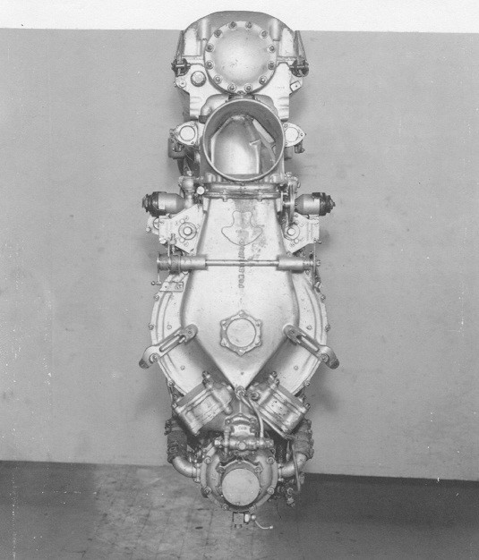
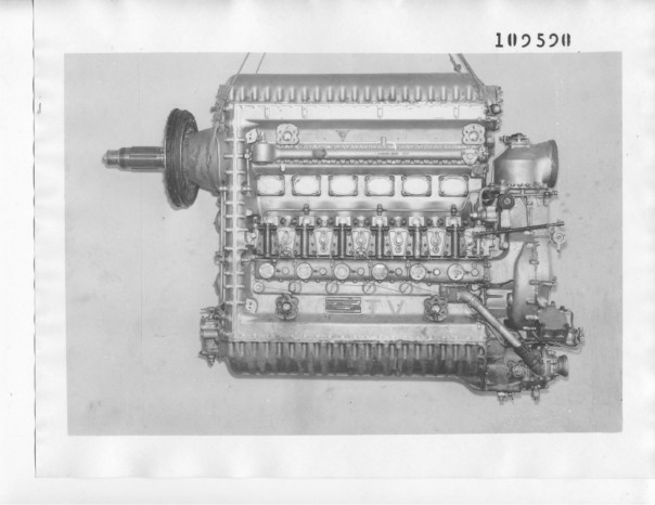
In March, 1943, Allied forces retrieved a 205C from a repair depot in Libya. The engine was shipped to McCook Field, where the U.S. Air Corps Material Air Command subjected it to a year-long series dynamometer tests. The resulting report– “Plant Laboratory Memorandum, Report No. Eng. 57-505-10” – provided much of the material that follows. I want to thank Kimble D. McCutcheon of the Aircraft Engine Historical Society for sharing this information and the photos that follow.
[1] Hirschel, Ernst, Aeronautical Research in Germany: From Lilienthal until Today, Horst Prem. Gero Madelung, p. 141
[2] Byers, Richard, “Power and Initiative in Twentieth Century Germany: The Case of Hugo Junkers,” Honors Degree program, Univ. of Adelaide, Australia, 1995, p. 23.
[3] Byers, footnote, p. 41.
[4] Vajda, Fereck A. and Peter Dancey, German Aircraft Industry and Production, 1933-1945, SAE, Warrendale, PA, 1998, ISBN 0-7670-0246-X, p. 254.
[5] Irving, David, The Rise and Fall of the Luftwaffe: the Life of Field Marshall Erhart Milch, 1973, p. 54, http://www.fpp.co.uk/books/Milch/Milch.pdf
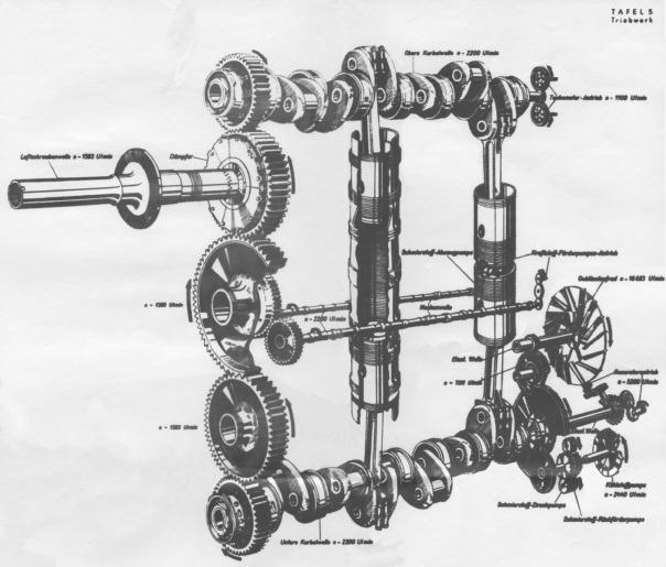
Crankshafts
A five-gear train connected the crankshafts. Drive gears bolted to the crankshaft noses and intermediate gears rode on anti-friction bearings. The lower crank drove the accessories – lube oil pressure and scavenging pumps and the heavily loaded blower. Injector camshafts, one on each side of the engine, ran off the upper idler gear. The portside camshaft also drove the high-pressure fuel pump and two lift pumps that were fuel through a third remotely mounted pump. Fuel lines, interconnected as a failsafe measure, ran along the length of both sides of the block.
Crankshafts were forged from chrome-nickel steel, similar to SAE 3135. Daimler M.A.N. and other German diesel designers avoided high-alloy crankshaft steels, since fatigue resistance was considered more important than wear life.
The exhaust, or upper, crankshaft led the lower, or intake shaft by 9⁰, an arrangement that converted top dead center from a geometric to a volumetric concept. It also enabled the exhaust ports to open before the transfer ports and close later to assure adequate cylinder filling and, quite possibly, some tiny supercharge effect.
Because the crankshafts turned in opposite directions, combustion forces acted on the lower shaft late, as its pistons were retreating. Consequently the upper exhaust-side crank developed more power. This reduced the stress on the timing gears, which was further reduced by bleeding power from the lower crank to drive the accessories. The upper crank, accounting for about 70% of engine output, drove the propeller.
The 205C exhibited “severe and violent vibration” during idle and coast down to stop. The 205C crank, with its long, narrow bearings and negative overlap between main and crankpin bearings, seems designed to twist. The designers viewed torsional vibration as a chronic condition. As Dr. Gasterstadt wrote, “Today we know it is impossible to keep the large speed range of an aircraft engine absolutely free from so-called critical vibration periods. It is only possible to keep the amplitude of the vibrations so small so that they are no longer dangerous.” [1]It is also true that crankshafts were the heaviest components of the 205C and every expedient was be taken to lighten them. Cranks were extensively drilled and, as on the early example tested at McCook Field, were innocent of counterweights. Later 205Cs had counterweights and a torsional damper on the air-screw drive.
Crankshafts ran on seven main bearings with Al-Cu inserts that could be replaced without major disassembly.
Cylinder liners
The liners evolved from those used on the 204 with flange nuts secured their lower ends to the cylinder block, helical grooves on the OD, and O-ring coolant seals.
Pistons
As indicated earlier, the traditional Junkers approach to piston design employed an oil-filled cavity to transfer heat from the crown to the piston rings and cylinder walls. While this arrangement seemed to work on earlier engines, the 205 developed more heat than the rings – narrow in order to flex as they pass over the cylinder ports — could transfer.
The response was to make the piston an insulator, rather than a conductor. Major features of the 7.005-lb assembly included:
- A deeply dished piston crown over which a ni-chrome steel fire plate was fitted. The dish, capped by the fire plate, contained nothing more than dead, and highly insulative, air. Four long bolts, nutted on their lower ends, held the fire plate in place. After experiencing bolt failures as the Y-alloy piston heated, Junkers installed a square-section coil spring on each bolt to compensate for thermal expansion.
205 pistons functioned as insulators.
- Piston rings followed the same philosophy used for the piston crown. That is, a fire ring isolated the compression ring stack from combustion forces. The gapless, L-shaped fire ring expanded under combustion pressure and heat to make firm rubbing contact with the cylinder walls. It rode on a Niresist insert cast into the piston. The M.A.N. VZ 32/44 double-acting two-stroke naval engine used a similar fire ring.
- The ring package varied. Some 205C engines had three compression and a single oil ring. The example tested by the U.S. Air Corps had five compression and two scraper rings, possibly as an attempt to reduce oil consumption. Pegs, secured by retainer rings, prevented the rings from rotating and catching on the cylinder ports.
- The wrist pin pivoted on 80 double-row needle bearings secured by retainer rings.
The high temperatures –1300⁰ F – resulting from an insulated combustion chamber resulted in good air-fuel mixing and were responsible for the exceptional level of fuel economy that characterized the 205C. But the cost was high. Gordon Murphy, a Fairbanks, Morse engineer and apparently a member of one of the teams that ferreted out German technology after the war, reported that “The solid top ring would work well when new and accurately fitted. As soon as wear took place (about 200 hours of operation) the ring would not seal properly, throwing the load on the second ring… [that would] run too hot and wear rapidly. Increased blowby followed by piston scoring would result in a short time.” (Appended to Rosen, C.G.A.,“German Diesel Engine Development,” SAE No. 470208, Jan. 1947, Vol. 1, No. 1, p. 160.) The field fix was to run the engine at reduced power.
Intake air
A centrifugal blower mounted aft on the cylinder block and driven from the lower crankshaft through 7:1 step-up gear train and manganese-bronze slip clutch to protect the fragile gearing during acceleration and shutdown, when cylinder compression stopped the engine after a few revolutions. The throttled air intake doubled as an emergency shutdown. The 9 5/8-in. diameter impeller consisted of 14 straight blades sandwiched between two aluminum discs. A 20-bladded stator converted air velocity to 19.3 psi absolute at the 2200 rpm rated engine speed. Output passed through ducts on either side of the engine and into air chests adjacent to the scavenge air ports. Port discharge ramps were angled to induce swirl.
With the engine turning 2200 rpm, the blower delivered 60% excess air at 40.3 in. Hg and, while doing so, consumed some 85 hp.
Injection
Two injectors, positioned 180⁰ apart, served each cylinder. Injectors were open, meaning that they took the form of open ports backed by check valves. The spring-loaded check valves set the minimum fuel pressure necessary to initiate injection and prevented cylinder compression from back flowing into the fuel circuit. However, these injectors were quite primitive when compared to the Bosch injectors used by other German manufacturers. That passengers and crew members found 205C smoke levels tolerable was the result of high cylinder temperatures.
Injection commenced at 11.5⁰ before tdc on the exhaust crankshaft and 20.6⁰ btdc on the intake shaft. The 0.1⁰ discrepancy was probably a measurement error, since the exhaust crankshaft led its mate by 9.0⁰. Air Force personnel did not determine the end of injection.
Injectors produced flat, sheet-like sprays of fuel that intersected at right angles to each other. Air “skittering” off the piston domes gave some protection against cylinder-bore washout, as did port-induced swirl. Fuel contact with the piston crowns was tangential and far less aggressive than discharge from the vertical injectors used on more conventional engines.
A pair of high pressure pumps, plumbed in parallel, fed the 12 injectors at peak pressures of between 7350 psi and 8620 psi. Helical slots in the pump plungers acted in conjunction with spill ports to regulate fuel delivery. Extending the rack increased the effective plunger stroke so that more fuel went to the injectors. In addition the pumps were staged. The starboard pump ran continuously with the port-side pump coming on line as fuel demand increased. At 2200 rpm and full power, the system delivered 105 lb of fuel per hour.
According to the factory, injection pumps were 100% redundant. Failure of one would have no effect upon power output. McCord personnel discovered differently: when one of three plungers on a pump stuck, output fell by 10%.
Surplus air
Operating under full load at 2200 rpm, the engine consumed 7500 lb/hr at sea level. Testers then imposed a restriction on the scavenge pump intake to progressively reduce air flow. No effect on power output was seen until airflow was reduced to 5000 lb/hr. This finding accorded with the factory statement that the engine ran with 60% excess air.
Lubrication and cooling
The lubrication system was conventional, consisting of a pressure pump delivering 63.5 lb a minute at 67 psi, and twin scavenging pumps. The engine exhibited specific oil consumption of between 0.013 and 0.027 lb/hp-hour. The engine’s healthy appetite for lube oil may have reflected its poor condition. Excessive oil consumption also had to do with the need to limit piston-ring tension in ported cylinders.
At 2100 rpm, no-load the lube oil absorbed 465 Btu/min, which is a remarkably low figure. At the same rpm, the glycol/water coolant absorbed 7500 Btu/min.
Performance
Personnel attached to the Power Plant Laboratory at McCook Field conducted a series of dyno tests on the engine at sea level and up to a simulated altitude of 20,000 ft. However, the simulation was less than perfect: while inducted air temperature and humidity accorded to conditions at altitude, exhaust gases vented at sea-level pressure. Initial calibration runs were made with a mixture of 95% kerosene and 5% motor oil. Subsequently the engine ran on Shell Diesolene, a paraffin-based distillate with a specific gravity of 0.852 at 59⁰ F and a heat content of 18,000 Btu/lb.
Sea-level calibration
| `hp | rpm | SFC lb/hp-hr (g/kW-hr) | Thermal efficiency (%) based on 18,500 Btu/lb fuel |
| 230 | 1000 | 0.382 (232) | 36.0%* |
| 300 | 1200 | 0.363 (221) | 37.9% |
| 365 | 1400 | 0.367 (223) | 37.5% |
| 415 | 1500 | 0.375 (228) | 36.7% |
| 447 | 1800 | 0.386 (235) | 35.6% |
| 487 | 2000 | 0.387 (235) | 35.6% |
| 525 | 2100 | 0.385 (234) | 35.8% |
| 548 | 2200 | 0.388 (236) | 35.5% |
*84.7% mechanical efficiency, the best recorded.
The best power output of 548 hp at 2200 rpm with 211.7 lb air/hour was significantly lower than the manufacturer’s claims of 592 hp (corrected from 600 pferdstark to SAE hp) standards). A sealed setscrew limited throttle motion and fuel delivery. It was deemed prudent not to change the factory setting.
Then and now
It’s instructive to compare the 85-year-old Junkers 205C with modern truck engine helps to put technological progress, or the lack of it, into focus.
Junkers 205C and the Volvo D-16 truck engine
| Junkers 205C | Volvo D-16 | ||
| Configuration | 2-stroke, opposed-piston inline six, DI | 4-stroke inline six, DI, turbocharged | |
| Displacement | 16.6 liter | 16.1 liter | |
| Power output | 548 hp @ 2200 rpm | Base rating 550 hp @ 2200 rpm | |
| Torque | 1650 – 1850 lb/ft @ 1100 rpm | 1850 lb/ft @ 1050 rpm | |
| Firing order | 1-5-3-4-2-6 | 1-5-3-6-2-4 | |
| Dry weight | 1200 lb | 3047 lb (1382 kg) | |
| Bore | 105 mm | 144 mm | |
| Stroke | 160 mm | 165 mm | |
| Compression ratio | 17.0:1 | 16.0:1 | |
| Bore-to-stroke ratio | 0.66 | 0.87 | |
| Cylinder center distance | 145 mm/ 1.38 x cylinder bore* | 186 mm/ 1.29 x cylinder bore | |
| Crankpin diameter | 49 mm/47% of cylinder bore | 99 mm/69% of cylinder bore | |
| Main bearing journal diameter | 63 mm/60% of cylinder bore | 108 mm/75% of cylinder bore | |
| Overlap between crankpin and main bearing diameters | 24 mm negative | 24.5 mm positive | |
| Main bearing length | 73 mm (est.)/length-to-diameter ratio 1.1 | 47 mm/ length-to-diameter ratio 0.43 | |
| Crankpin bearing length | 35 mm (est.) length-to-diameter ratio 0.78 | 57 mm/length-to-diameter ratio 0.58 | |
| Injection pressure | 7350 -8820 psi | 35,000 psi (2400 bar) |
*Modern practice is to hold cylinder centers to 1.2 times bore diameter and less when cylinders are siamized. 205C crankshaft dimensional data is taken from Pirault and Flint.
[1] “Development of the Junkers Aircraft Engine,” NACA Technical Memorandum No. 565.
